Search

What Is an API Tank and How Is It Used?

An API tank is an engineered storage vessel built around recognized American Petroleum Institute requirements. The term usually describes tanks designed, fabricated, inspected, or maintained under standards such as API 650 or API 12F. These standards guide shell thickness, welding, roof construction, materials, testing, and inspection. They do not replace engineering judgment.

Philip E. Myers, a respected storage-tank author, wrote, “A storage tank is only as reliable as its weakest detail.” That warning remains practical. A thick steel shell cannot compensate for a poor foundation, blocked vent, damaged coating, or neglected inspection point.

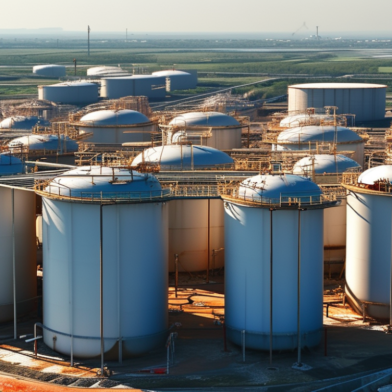
In real facilities, api tanks may hold crude oil, chemicals, water, fuel, or other compatible liquids. Their design depends on capacity, temperature, vapor pressure, fluid chemistry, wind, seismic conditions, and operating cycles. A floating roof can reduce vapor losses. A fixed roof may suit less volatile products. Bund walls and drainage systems help control accidental releases.

The details become visible during operation. Inspectors may find coating blisters near the bottom course, moisture beneath insulation, or settlement around a tank stairway. Small signs matter.

API tanks also require disciplined maintenance. Operators monitor corrosion, leaks, roof seals, vents, welds, and foundations. Inspection intervals should reflect service conditions, not habit alone.

The label “API tank” sounds simple. It is not. Compliance depends on the complete lifecycle, from site preparation to retirement. A standard can organize decisions, but it cannot notice every field mistake. That responsibility still belongs to competent engineers, inspectors, and operators.
What Is an API Tank and How Is It Used?

Definition and Core Purpose of an API Tank

What Is an API Tank and How Is It Used?

An API tank is a storage tank designed, built, or inspected according to standards published by the American Petroleum Institute. Its core purpose is controlled storage of liquids under defined operating conditions. These liquids may include crude oil, refined products, water, or other industrial fluids. The tank usually has a welded steel shell, a fixed or floating roof, vents, access openings, and monitoring points. Its size and design depend on liquid properties, temperature, pressure, and site conditions.

In daily operations, an API tank receives liquid from pipelines, processing equipment, or transport systems. Operators monitor the level, temperature, pressure, and signs of leakage. A floating roof can reduce vapor space and limit product loss. Secondary containment helps control accidental releases around the tank. Regular inspections examine corrosion, welds, foundations, roof seals, and safety devices. Small details matter. A blocked vent can create serious pressure problems. Poor drainage can weaken the foundation over time.

API compliance is not simply a label placed on the shell. Engineers must match the tank design with its intended service and operating limits. In practice, the picture is less tidy. Older tanks may have incomplete records or unexpected corrosion. That requires careful assessment, not assumptions. A properly managed API tank supports safer storage, predictable maintenance, and more reliable plant operations.

Key Components and Structural Design of an API Tank

An API tank usually refers to an API oil-water separator used in industrial wastewater treatment. Its structure supports gravity separation, not chemical treatment. API Publication 421 commonly uses a 150-micrometre oil droplet as a design reference. The tank therefore needs calm, evenly distributed flow.

The inlet diffuser reduces turbulence before water enters the separation chamber. Baffles guide the flow and protect the surface from short-circuiting. A floating skimmer removes accumulated oil, while a sludge hopper collects heavier solids. The outlet weir controls water depth and discharge stability. Access covers, vents, drains, and sampling points also require careful placement.

Structural design matters. Engineers check tank length, width, depth, freeboard, corrosion allowance, and operating temperature. API Standard 650 provides widely used guidance for welded steel tank construction, although an API separator may also use reinforced concrete. The American Petroleum Institute’s guidance stresses predictable hydraulic loading and maintainable internals. Real sites behave less neatly. Rainwater, emulsions, and sudden flow changes can reduce separation efficiency. I would not treat retention time alone as proof of performance. The U.S. Environmental Protection Agency’s industrial wastewater guidance repeatedly emphasizes monitoring, inspection, and process-specific controls. A practical design needs those habits, not only a strong shell.

How an API Tank Separates Oil from Wastewater

An API tank is a gravity-based separator designed to remove free oil from wastewater. The name refers to standards developed for petroleum wastewater treatment. Inside the tank, wastewater moves slowly through a wide chamber. This reduced velocity gives oil droplets time to rise. Heavier solids settle on the bottom.

The separation process is simple, but careful design matters. Floating oil gathers near the surface and moves toward a skimming device. Scrapers or rotating skimmers guide it into a collection trough. Clarified water then flows beneath the oil layer and exits through an outlet. Sludge collects in the bottom zone and requires controlled removal. Small details matter. Uneven flow can disturb the oil layer and reduce separation efficiency.

In field operations, technicians should check inlet turbulence, oil thickness, sludge depth, and outlet clarity. Sampling both influent and effluent helps confirm actual performance. A clear surface does not always mean clean water. Dissolved oil, detergents, and very small droplets may pass through the tank. This is a common limitation. Chemical treatment or additional filtration may be needed afterward. Regular inspection also prevents clogged skimmers and excessive sludge buildup. API tanks work best when operators adjust flow carefully and record changing wastewater conditions. No separator performs perfectly under every load.

What Is an API Tank and How Is It Used? — How an API Tank Separates Oil from Wastewater

An API tank, commonly called an API oil-water separator, uses gravity separation to remove free oil and settleable solids from wastewater before downstream treatment.

System Area Data Dimension Typical Value or Range How It Works or Why It Matters
Basic Function Primary treatment objective Removal of free oil, grease, and settleable solids The tank reduces the contaminant load entering biological, chemical, dissolved-air flotation, or polishing treatment units.
Separation Principle Gravity separation Oil rises; solids settle Oil droplets with a density lower than water move upward, while particles denser than water move downward when the flow is sufficiently calm.
Tank Configuration Flow path Horizontal, longitudinal flow Wastewater moves through a long settling chamber at a controlled velocity, allowing oil droplets and solids time to separate from the water phase.
Hydraulic Design Typical hydraulic retention time Approximately 30–60 minutes The actual design value depends on flow variation, oil droplet size, temperature, viscosity, solids loading, and required effluent quality.
Hydraulic Design Flow velocity Low and non-turbulent; often about 0.6–0.9 ft/min (0.18–0.27 m/min) A low horizontal velocity helps prevent resuspension of settled solids and reduces turbulence that could break oil into smaller droplets.
Oil Removal Oil form most effectively removed Free and gravitationally separable oil API tanks are effective for relatively large, dispersed oil droplets but are not designed to remove stable emulsions or dissolved hydrocarbons without additional treatment.
Oil Removal Surface collection Skimmer, scraper, or overflow collection system Separated oil accumulates at the water surface and is periodically or continuously collected for storage, recovery, or further processing.
Solids Removal Bottom collection Sludge hopper, scraper, or sludge pump Heavier suspended solids settle to the tank bottom and must be removed regularly to preserve effective volume and prevent anaerobic buildup.
Pretreatment Inlet screening and grit removal Recommended where debris or coarse grit is present Preliminary removal of large debris and abrasive grit protects skimmers, scrapers, pumps, and downstream equipment.
Performance Typical free-oil reduction Often about 50–90%, depending on influent conditions Removal efficiency varies significantly with droplet size, oil concentration, emulsification, temperature, hydraulic loading, and maintenance practices.
Effluent Quality Common remaining oil concentration Frequently designed in the range of 50–100 mg/L for conventional gravity separation This is a planning range rather than a guaranteed result; discharge requirements may require coalescers, flotation, filtration, or other polishing processes.
Monitoring Important operating indicators Influent flow, oil layer depth, sludge depth, pH, temperature, and effluent oil concentration Routine monitoring identifies hydraulic overloading, excessive sludge accumulation, poor skimming, and changes in wastewater characteristics.
Maintenance Oil and sludge removal frequency Based on layer thickness and solids accumulation; commonly scheduled inspections are required Removing accumulated oil and sludge prevents carryover, reduces odors, maintains retention volume, and protects separation performance.
Limitations Contaminants not efficiently removed by gravity alone Dissolved hydrocarbons, stable emulsions, very fine droplets, and soluble contaminants Additional chemical, physical, or biological treatment may be needed when wastewater contains emulsified or dissolved pollutants.
Typical Applications Industrial wastewater sources Petroleum handling areas, vehicle maintenance facilities, metalworking sites, and process-drain systems The separator is installed where wastewater may contain free oil and suspended solids that can be removed by a calm gravity-settling process.
Note: The values shown are typical engineering reference ranges, not universal design criteria. Final sizing and performance requirements should be established from site-specific flow data, wastewater testing, temperature, oil properties, regulatory limits, and applicable design standards.

Operating Procedures and Essential Maintenance Practices

An API tank stores liquids under controlled atmospheric or low-pressure conditions. Its safe operation begins with a clear inspection routine. Operators should confirm the product level, temperature, pressure, and tank condition before transfer. Check valves, vents, gauges, and emergency shutoff points. Keep the surrounding area clean and free from ignition sources. Grounding connections must remain secure during loading and unloading.

Never trust a quiet tank. During operation, watch for unusual odors, shell deformation, leaking flanges, or sudden level changes. Compare gauge readings with manual measurements when practical. A mismatch may indicate instrument failure, product loss, or an internal problem. Operators should use suitable protective equipment and follow site-specific entry controls. Tank entry requires isolation, atmospheric testing, ventilation, and trained personnel. It should never become a casual shortcut.

Maintenance works best when records are specific. Inspect the roof, shell, bottom area, ladders, platforms, coatings, and foundation at planned intervals. Remove water and sediment when procedures allow, then examine corrosion beneath deposits. Test alarms, vents, overfill protection, and fire-response equipment. Small rust spots deserve attention before they become structural defects. This is where many programs become too confident. A completed checklist does not prove a tank is healthy. Maintenance teams should document measurements, photographs, repairs, and changing trends. Independent inspections may also reveal problems that routine operators overlook. Recheck assumptions after severe weather, unusual vibration, or any product change.

API Tank Operating Procedures and Inspection Intervals

API 650 tanks are commonly operated with routine visual checks, controlled filling and withdrawal, overfill protection, leak monitoring, and documented maintenance. API 653 establishes inspection intervals for in-service tanks; the actual interval may be shorter when corrosion rates, service conditions, or risk assessments require it.

Reference basis: API 653 commonly limits periodic external inspections to no more than 5 years and internal inspections to no more than 20 years, subject to corrosion-rate calculations and other applicable requirements. These values are planning limits, not a substitute for a site-specific inspection program.

Applications, Safety Considerations, and Selection Criteria

An API tank is an aboveground steel storage vessel designed around recognized engineering requirements. It commonly holds crude oil, refined products, water, or compatible industrial liquids. In field operations, its value is practical: a tank provides controlled capacity near receiving, processing, or loading areas. Fixed-roof tanks suit lower-volatility liquids, while floating-roof designs can reduce vapor space and emissions. The application determines more than capacity. Liquid properties, temperature, pressure, turnover rate, and site conditions also shape the design. Small details matter.

Safety begins with a documented hazard review, not with the tank shell alone. Operators should verify foundation settlement, weld condition, corrosion, vents, overfill protection, grounding, and access routes. Inspection intervals should reflect service conditions and applicable codes. A clean-looking exterior proves little. Leak detection, secondary containment, emergency isolation, and clear operating procedures support safer use. Workers need task-specific training and suitable protective equipment. Flammable liquids require controlled ignition sources, vapor management, and carefully selected electrical equipment. In practice, assumptions can fail. A vent may be blocked. A foundation may shift unnoticed.

Selection should compare working volume with usable volume, allowing room for thermal expansion and operational changes. Engineers should confirm material compatibility, design temperature, wind and seismic loads, roof type, nozzle arrangement, and inspection access. Local environmental and fire requirements may add controls. Procurement records should include drawings, calculations, inspection reports, and material certificates. Cost alone is a weak filter. A cheaper tank can demand more maintenance or create difficult inspection conditions. No design is perfect. Site experience should challenge the specification before fabrication begins.